How Can We Help?
Color or Highlight Clipping Artifacts with Bright Colored Lights
Note:
Note: The matrix described in this article is no longer recommended as the best solution. ACES 1.3 introduces a new and improved solution to this issue with a Gamut Compression LMT.
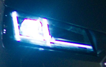
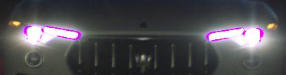
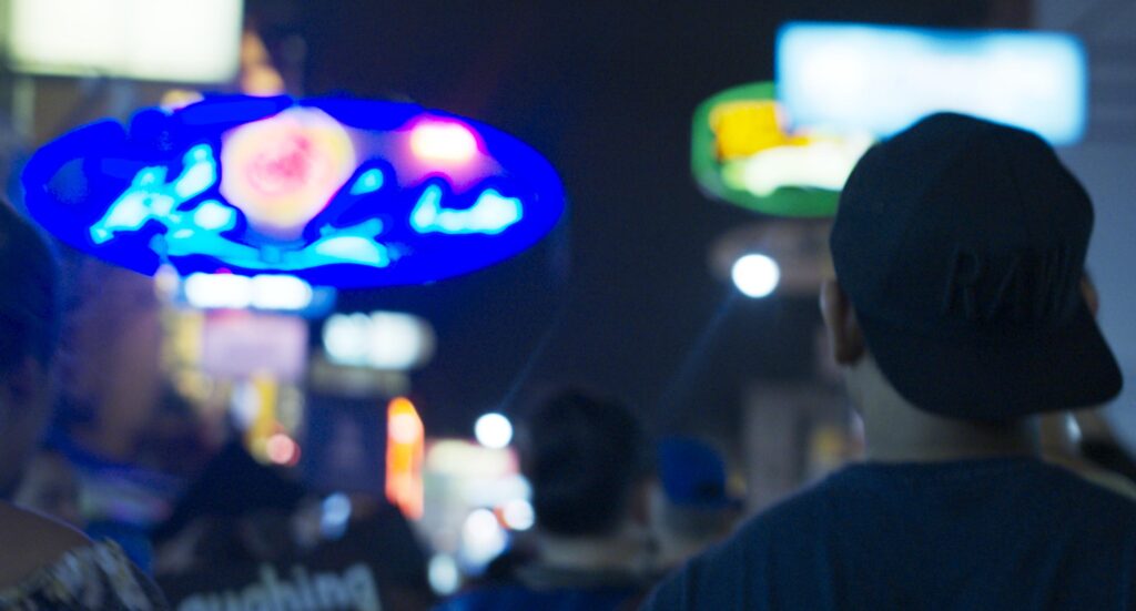
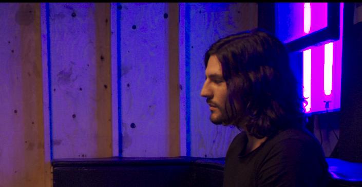
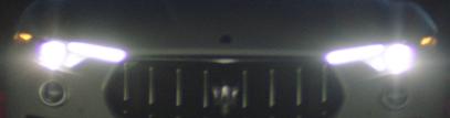
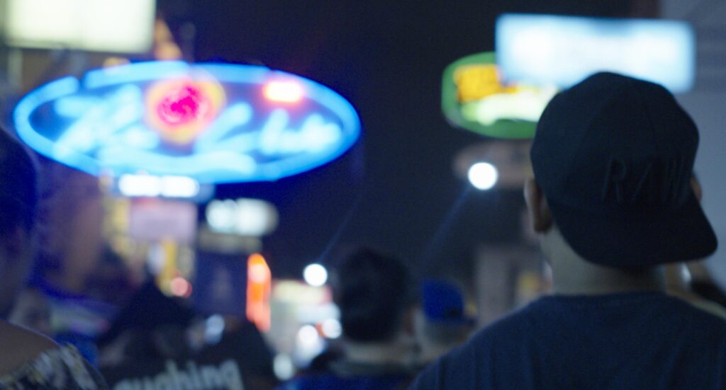
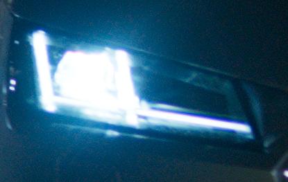
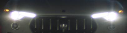
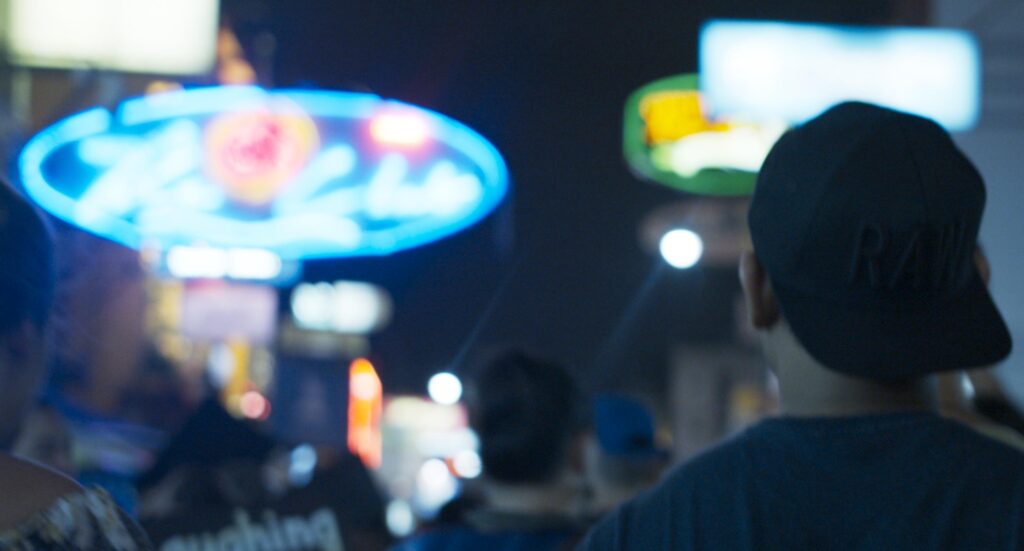
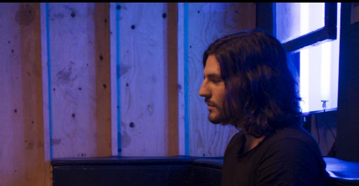
The issue usually appears when LEDs or brightly colored lights are shot directly into the camera. Depending on the lens and capture scenario, the camera can “see” these colors in a way that produces problematic colorimetry for some of the later ACES color transforms.


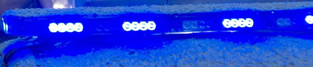
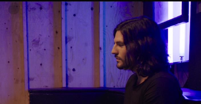
In this particular example, the blue sirens are bright but not fully saturated relative to AWG RGB encoding space. The ARRI LUT applies a tone-scale in the AWG RGB space, and because the values are not fully saturated, they render “gracefully” through the tone-scale. Relative to AP1, however, these blue sirens are much more saturated. It’s this difference in saturation relative to the RGB space in which the tone-scale is applied that is preserved through the ACES rendering. The rendering has no knowledge of the input encoding – it just works on whatever RGB is fed into it.
A corrective Look Transform (LMT) was created that helps desaturate blue hues in order to reduce this artifact where bright blue colors (e.g. sirens, headlights, LED lighting, etc.) may become oversaturated or exhibit hue shifts as a result of clipping.
The LMT is a simple 3×3 matrix transform and can be inserted when this issue is encountered. In most cases, it should allow you to continue working with ACES on these shots. A more robust and longer term solution is being tackled by the Gamut Mapping VWG and ACES 2.0 will address this.
The matrix in standard “textbook notation” is as follows:

For convenience, the matrix is provided in a CTL transform and in a DCTL for use in Davinci Resolve. The matrix is also provided in Resolve via “LUTS > CLF > LMT Neon Suppression”.
As a simple 3×3 matrix, the transform is trivial to add manually to other software workflows that don’t support CTL or DCTL but allow for insertion of a 3×3 matrix. Note, however, that this matrix in designed to be applied to linear ACES data (AP0) and prior to any Output Transform.
Examples
The following examples show comparisons between the ACES rendering demonstrating the artifact (left), the way the image is handled through the default ARRI rendering (middle), and ACES with the 3×3 Look Transform applied (right).