Thursday, February 20, 2020
9:30am - 10:30am PST (Los Angeles time / UTC-05:30pm)
Please join us for the next meeting of this virtual working group (VWG).
Dropbox Paper link for this group:
We will be using the same GoToMeeting url and phone numbers as in previous groups.
You may join via computer/smartphone (preferred) which will allow you to see any presentations or documents that are shared or you can join using a telephone which will be an audio only experience.
Please note that meetings are recorded and transcribed and open to the public. By participating you are agreeing to the ACESCentral Virtual Working Group Participation Guidelines
Audio Only
You can also dial in using your phone.
Dial the closest number to your location and then follow the prompts to enter the access code. United States: +1 (669) 224-3319 Access Code: 241-798-885
@daniele: You mentioned that you tried stuff that did not work already. I think it would be fantastic to make that available (if possible) to the group, especially if it avoids going into dead-ends.
@matthias.scharfenber: I cannot quantify yet how hard it would be to change Mitsuba to be able to use different sensitivities, probably easy, the hardest part would be the spectral upsampling method. It uses Smits (1999) which generates square pulses.
We don’t really need a renderer anyway, it would just help to produce better looking pictures
I think it was the 2006 to 1931 bridge.
We did not find a satisfactory and robust conversion between the two yes, which had not out of gamuts colours in either of the two places. Even with non-linear mappings.
So if we go 2006 we need to go all-in. But I thought we have decided to leave this discussion out for now?
CIE 2006 .pdf (226.3 KB)
Sorry for leaving the meeting earlier. I wanted to come back to the issue of using other CMF’s. I don’t see how using CIE 2006 CMF would improve things. Camera RGB sensitivities are far too different. I have pasted together a few figures.
Pages 2 and 3 show the CIE 1931 and 2006 CMF respectively. Page 4 are the spectral sensitivity of a motion picture camera. I won’t say which one. All are balanced for equal energy white.
Page 5 is a matrix fit of the camera to the CIE 1931. This would be an IDT that is not based on relevant stimuli but attempts a best spectral match. Page 6 shows the resulting chromaticity errors for a set of 190 test stimuli that were suggested by the ACES IDT authoring guide.
Page 7 and 8 show the same situation with the CIE 2006 CMF. As you see it does not change much.
Using the CIE 2006 CMF will give you neither a better color reproduction of surface colors nor a better mapping of monochromatic stimuli.
Thanks Harald, this is very useful.
Finally we get some quantitative figures (Using 2006 would not magically result in better simple IDTs).
I think we would still benefit from more elegant intermediate spaces and maybe better prediction of metameric pairs. But this is also not quantified yet, afaik.
A few questions, what does Balanced for EE means here, is it to center the CMFs somehow? I’m assuming you computed a 3x3 matrix between the two sets of coordinates but without seeing the maths or code it could be anything.
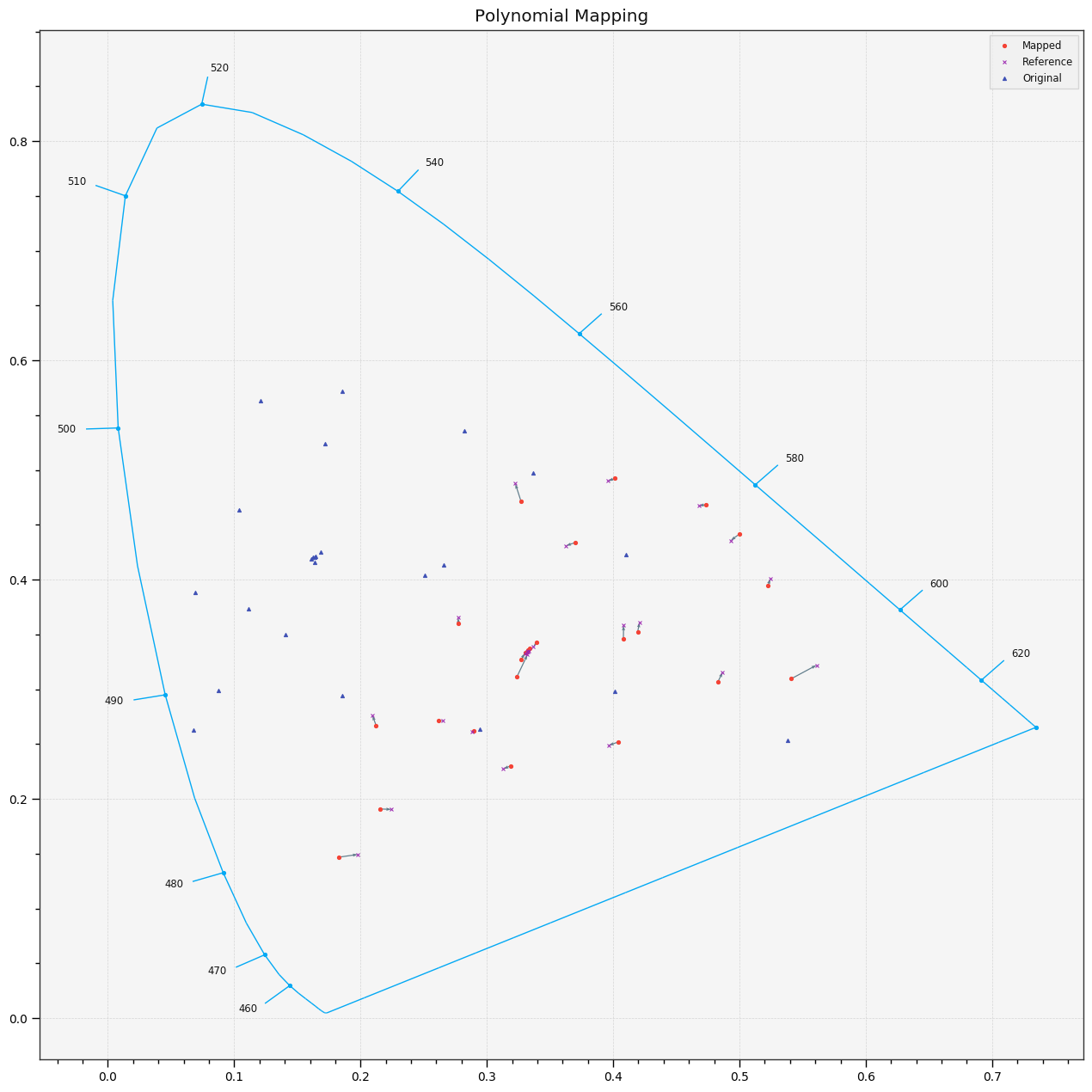
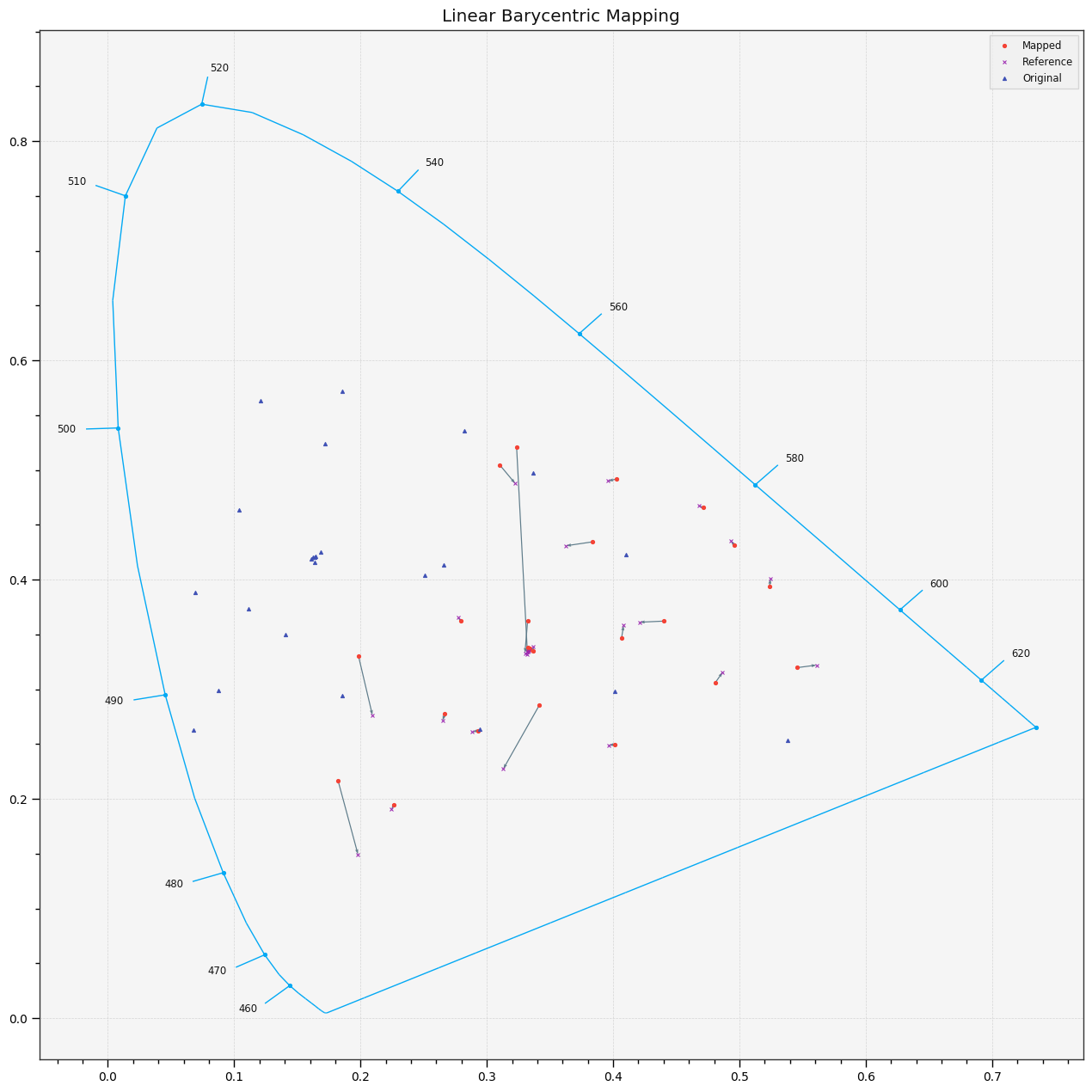
I have been adapting a notebook from last year that I will share as soon as I have good results. I got decent results with polynomial fitting between CIE 1931 and some Hasselblad Sensitivities and I’m trying another method, i.e., Delaunay based interpolation, that has not succeeded very well so far.
sorry for being so cryptic. The CMF’s are balanced for EE, the equal-energy spectrum. It simply means that the sum of each channel is the same. For comparison, I did the same for the camera sensitivity.
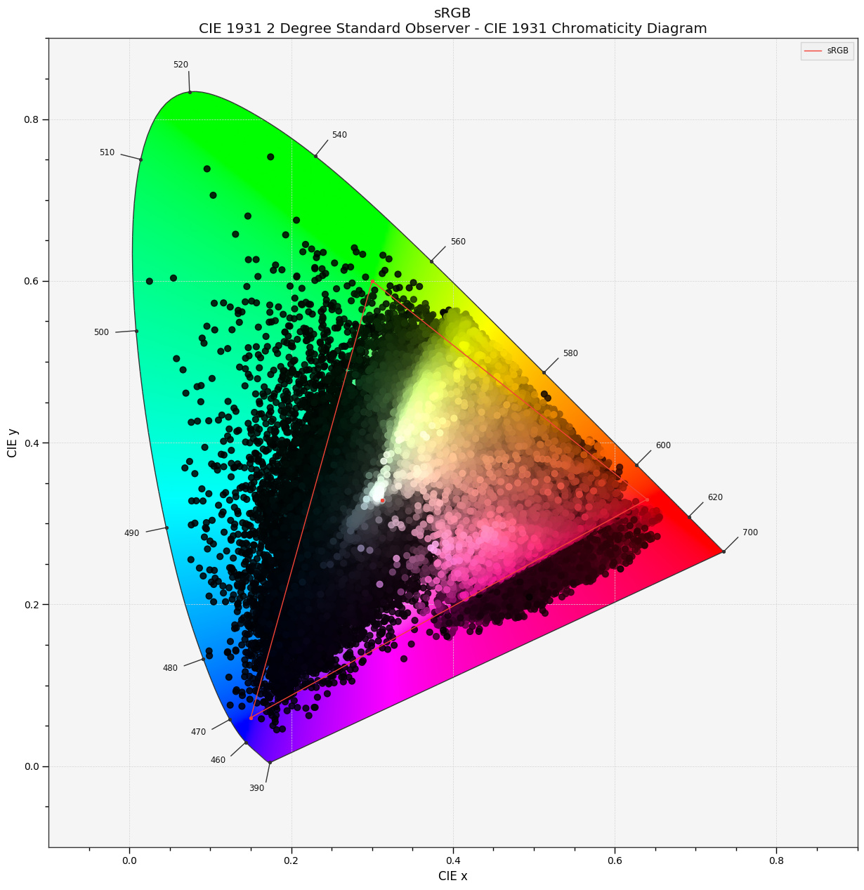
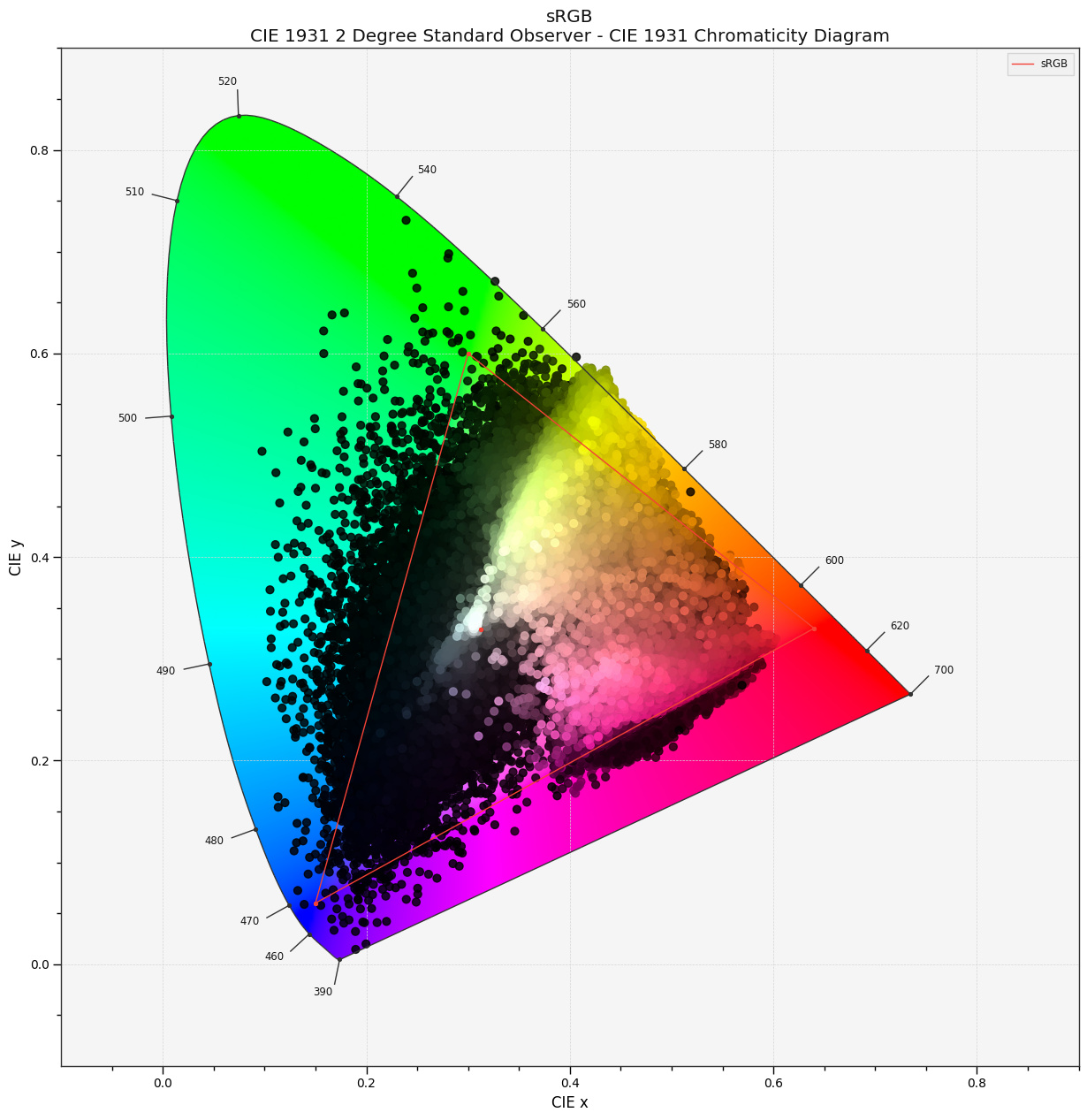
I did not fit a 3x3 matrix between the two CMF’s but between the camera sensitivity and the CMF’s. That is equivalent to an IDT based on zero knowledge about the stimuli. Then applying this IDT to the 190 test stimuli yields the two figures on pages 6 and 8, where the open circles are the chromaticity coordinates of the stimuli in CMF. The red * are the chromaticity coordinates from the transformed Camera RGB values. I wanted to show that the color reproduction error isn’t reduced by switching from the 1931 to the 2006 CMF.
Yes, you can fit a higher order polynomial from some camera sensitivity to the CMF. But then your IDT is not linear, which means it’s not exposure-invariant anymore. In order to maintain linearity you would need to use Finlayson’s root polynomials (google it, the first hit is the paper)
BTW, I propose that any transform T of scene-referred data shall be exposure-invariant, which means linearity: T(ax) = aT(x). This includes gamut-mapping.
Also the transform shall be balance preserving, which is probably not a limitation for any gamut-mapping algorithm.
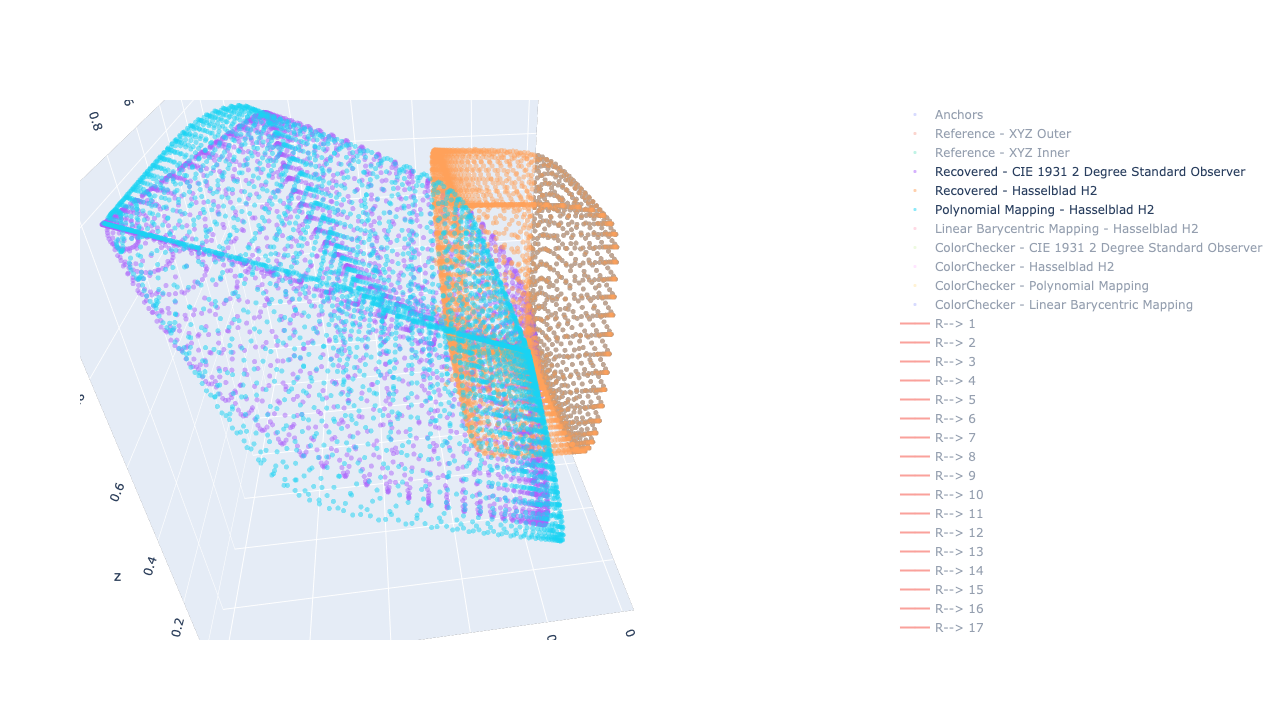
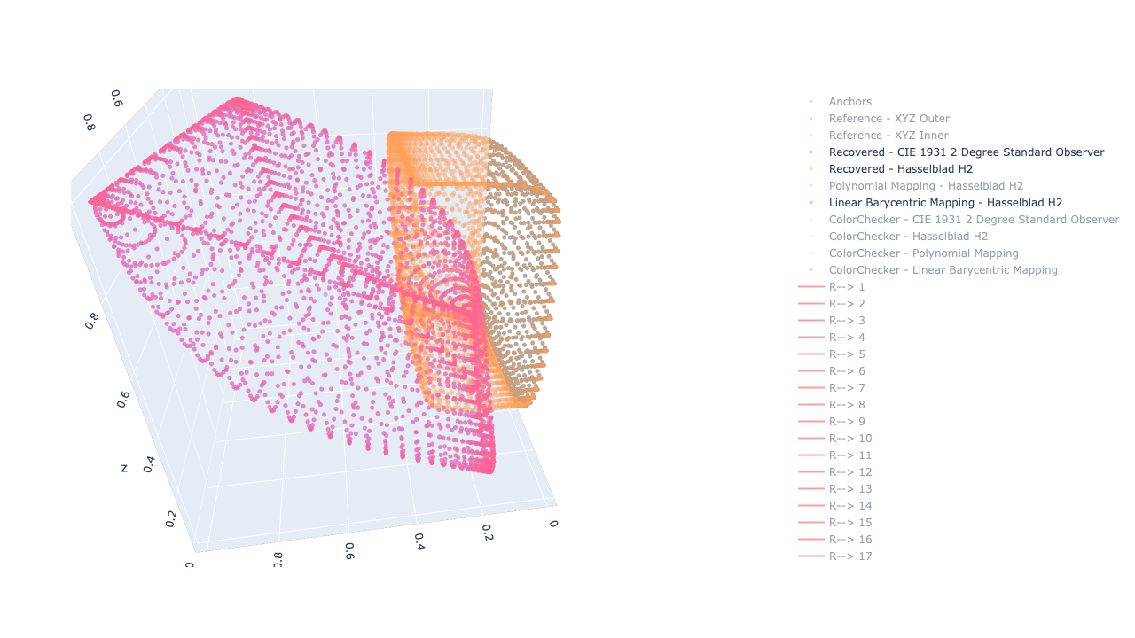
I will document it better and there are a few TODOs, but the core idea, as discussed during the meeting, is to spectrally generate points in the respective camera sensitivities and observer volumes and morph between them.
count    24.000000
mean      0.018311
std       0.016151
min       0.001531
25%       0.004763
50%       0.014945
75%       0.022761
max       0.059692
Name: Polynomial Mapping, dtype: float64
*******************************************************************************
count    24.000000
mean      0.032965
std       0.029378
min       0.004952
25%       0.014112
50%       0.023596
75%       0.040225
max       0.123378
Name: Linear Barycentric Mapping, dtype: float64
So obviously, ANYONE can make a copy of that notebook online and run it. The Google Colab VMs are a bit slow but it is easy to run it on a beefy CPU VM on GCP, I have done it over the weekend. I might redo it to generate a dense spectral distributions grid as it is a bit slow when reconstructing 10 of thousands of them.
Tomorrow, I will create another notebook to generate programmatically spectral imagery, maybe based on the METACow or something fancier, e.g. the Oscar character
Cheers,
Thomas
PS: The notebook is not guaranteed to be free of defects, especially after the cleanup.
the root polynomial might improve the color reproduction, but it won’t solve the issue of gamut-mapping. Attached is a document showing the results of two fits of the aforementioned motion-picture camera to the 1931 observer using the 2. and 3. degree root polynomial. While one could probably improve the results along the purple boundary, there will be still stimuli mapped outside of the monochromatic locus. RootPolynomial.pdf (96.2 KB)
I wonder if a discussion about new IDT’s is within the scope of this work group. I understand that the envisioned architecture is based on an encoding and a working color space. This group hopefully comes up with a transform that gracefully maps from the former to the latter. This would leave it in the responsibility of the camera’s manufacturer to provide an IDT that maps the sensor signal into the encoding color space.
Yes I saw that the Camera Sensitivities are still not fitting within, (visible in the notebook 3D plot if you enable the first scatters), they should however with the linear barycentric interpolation, they will be distorted exactly to match the CMFs.
I’m exploring that stuff from the IDTs side because this is where the problem comes for the cameras. There might be a piece-wise transformation where for example, colours inside Pointer’s are handheld by the current IDTs and everything outside is gracefully blended via another transformation, e.g. the Linear Barycentric one so that you preserve as much as possible of the current look. This would effectively result in different IDTs.
I’m hopeful for an algorithm to fix the issue after the fact but there is some merit at looking that they don’t happen in the first place, if that makes sense.
I have a few sources I can pull data from which I will do over the weekend to build a collection. There is still value to generate some synthetically and I have yet another computational notebook for that here although I would prefer having some offline renders: https://colab.research.google.com/drive/1Zm1QSVJG09uWkkarZLCtLi_xPzCC4Gof
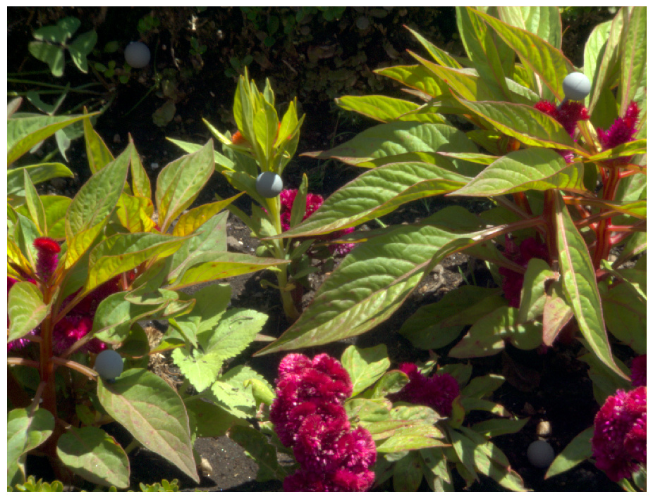
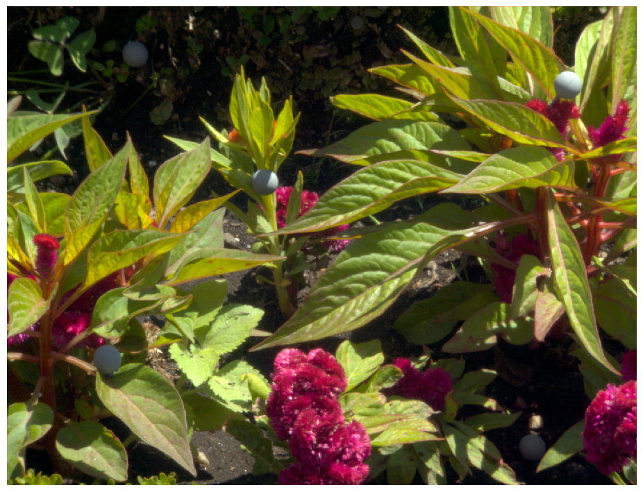
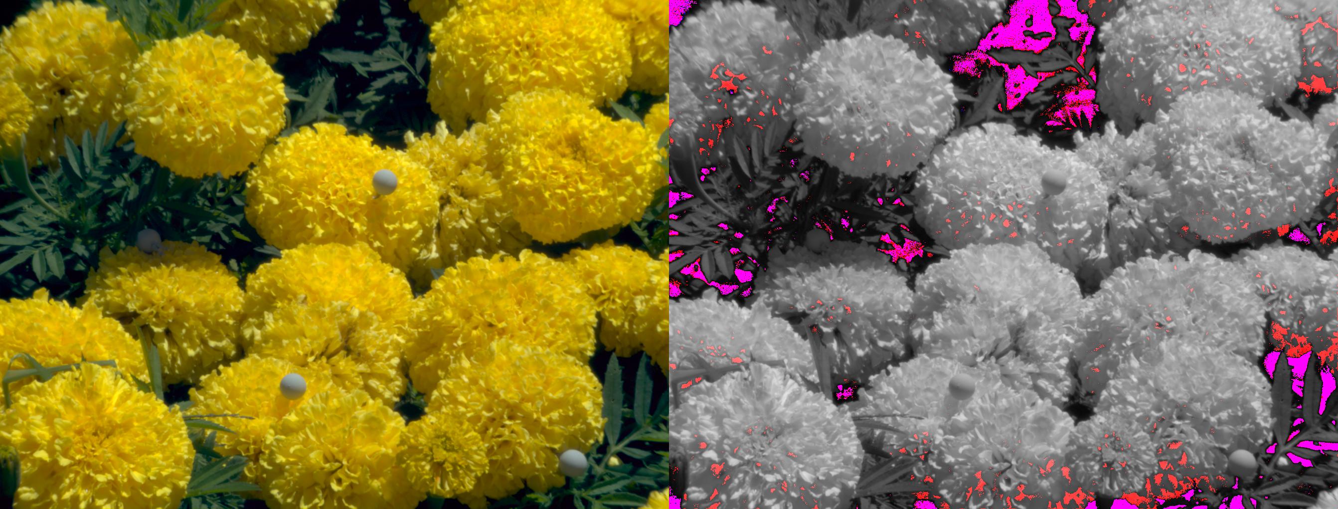
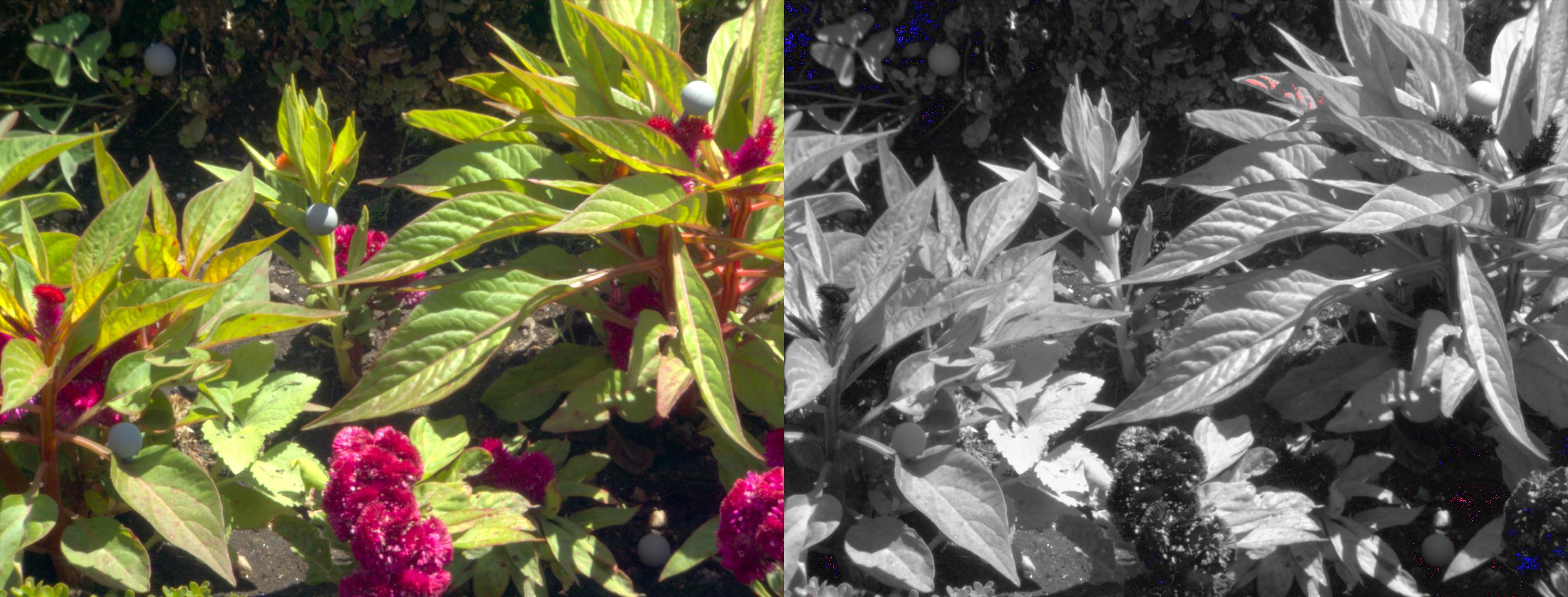
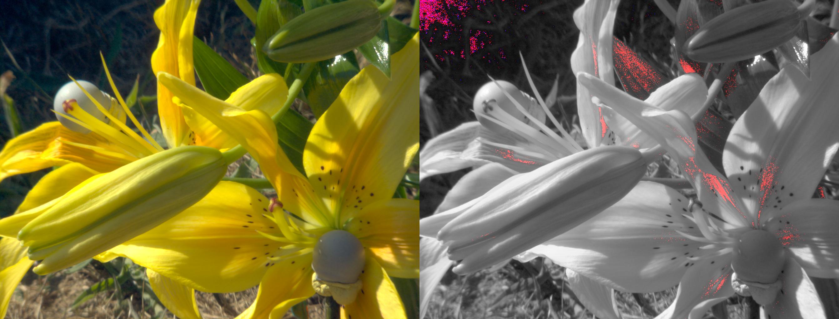
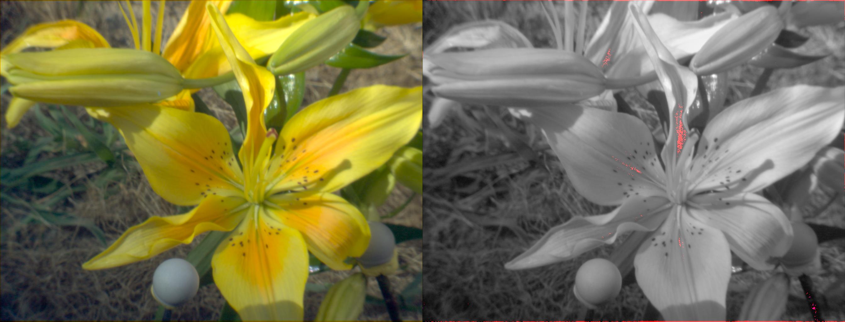
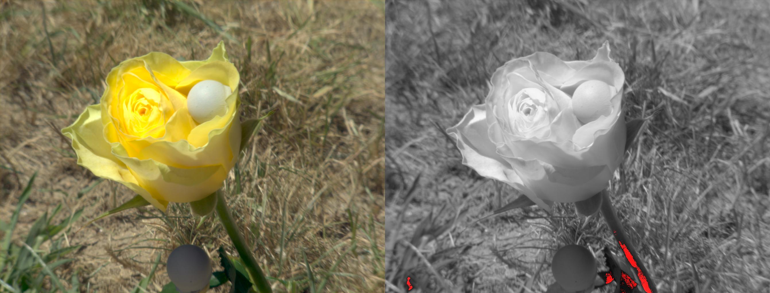
the images do not contain much content outside of AP1 (many of the chromaticities outside of the gamut are caused by noise). Here are a few images. On the left hand side is the original image (generated from the scene XYZ using D65 as illuminant). On the right hand side is an grayscale version. Marked in red are areas where the ALEXA maps it outside of AP1 and marked in blue are areas where the original scene color is outside of AP1.
I know right!? Quite disappointing! I have pulled down most of their content to check that and see if there are good candidates, I don’t have high hopes given how the content seems to lack of colourfulness. That being said some cameras might surprise us!
I’m wondering if it would be worth for the Academy to rent a hyperspectral camera and shoot an image that is purposely designed to generate offending colours, e.g. narrowband LED lights on shiny surfaces, flowers, fruits, car paints and fluorescent materials. It is most likely easier (and cheaper) to setup a single camera for that than 10 or 15 different ones. It is maybe a case of just contacting those researchers which I will!
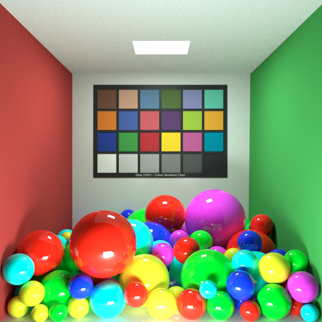
The other obvious path is synthetic imagery where it is trivial to generate offending data.
I just sent an email on behalf of the group to David Foster asking if he knows about any colourful hyper-spectral image or would be willing to help us producing one.
I think most problems in the ACES workflow were caused by self-luminous objects, mostly LED’s in these days.
Does anyone have examples with object colors?
I don’t have any hyper-spectral imagery with that type of stuff, I CCed you to the mail I sent to David Foster, keen to see his reply.
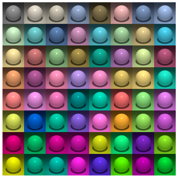
Absolutely! I will poke at that tonight in my synthetic notebook sphere stuff. I will also look at setting up a PBRT scene for that later, I made a spectral scene like that for Mitsuba last year or so but it was in Maya, so I would need to redo it in a way that is easy to render for everybody: