Look Modification Transforms (LMTs) are a very powerful component of the Academy Color Encoding System and offer extraordinary flexibility in ACES-based workflows. This multi-part post will explain what LMTs are, why they are so important, and how they can be constructed and applied.
For those interested in perusing existing LMT documentation, please see Academy TB-2014-010.
So what exactly are LMTs?
LMTs provide a mechanism to apply an infinite variety of “looks” to images in ACES-based workflows. LMTs are always ACES-to-ACES transforms. In other words, ACES2065-1 data directly translated from camera-native image data via an Input Transform is manipulated by the LMT to output new ACES2065-1 data (designated in diagrams as ACES’) that is then viewed through an ACES Output Transform.

LMTs can be used to set a “starting look” that is different from the default rendering associated with an ACES Output Transform. Any adjustment away from the starting default reference rendering is considered a “look” within an ACES framework. By this definition, a “look” can be as simple as ASC CDL values preserved from set to define a starting grade.
LMTs can also be used project-wide to reduce contrast and saturation across all shots, providing what might be a more preferred starting point for colorists accustomed to flatter and more muted starting images.
LMTs can also encapsulate a preset creative look. Very complex creative looks, such as film print emulation, are more easily modeled in a systematically derived transform than by asking a colorist to manually match using only the controls in a color corrector. Having a preset for a complex creative look can make colorists’ work more efficient by allowing them to quickly get the creative look they (and the filmmaker) want, and to spend more time on shot- and/or region-specific creative color requests from clients.
Over time, a collection of LMTs may be collected into a “library of looks” that can be used to apply an initial grade or a “show LUT” look on any given project. Further grading adjustments can be made on top of the new starting point. LMT’s are image-wide; they cannot capture power windows, mattes, etc.
Rendering
Generally speaking, camera-native image files from today’s digital motion picture cameras do not look “correct” when viewed directly, as they are “unrendered.” Camera-native image files are typically encoded in a manufacturer-specific RGB space metric and log encoding, which have been designed to preserve as much of the captured scene information available from the camera’s image sensor.
For example, ARRI uses ALEXA WideGamut/Log C, Canon has Cinema Gamut/Canon Log 2, Panasonic created V-Gamut/V-Log, RED defines REDWideGamutRGB/Log3G10, Sony utilizes S-Gamut3/S-Log3, and so on.
These camera-native images are not intended to be viewed directly without some amount of processing. In order to create pleasing images, camera-native image files must be processed through a camera-specific rendering transform.
Film
For example, traditional film scans (Cineon Log) were viewed through print film emulations (PFEs), most of which were also proprietary to a particular post-production facility and may have been part of that facility’s “secret sauce.”
Let’s take a look at a Cineon-encoded DPX film scan. The image on the left appears flat and desaturated because it is presented in its native state – as an unrendered log-encoded image. But Cineon images were typically viewed through a PFE, so on the right is the same image as rendered by a PFE. Note that the rendered image has more contrast and saturation, improving our perception of the image as being a more “accurate” and pleasing reproduction of the photographed scene.

Digital
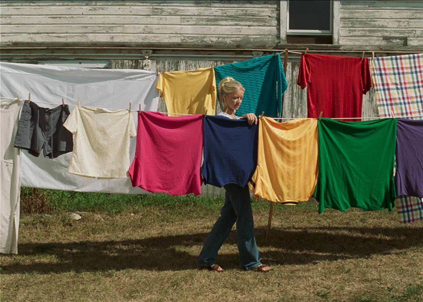
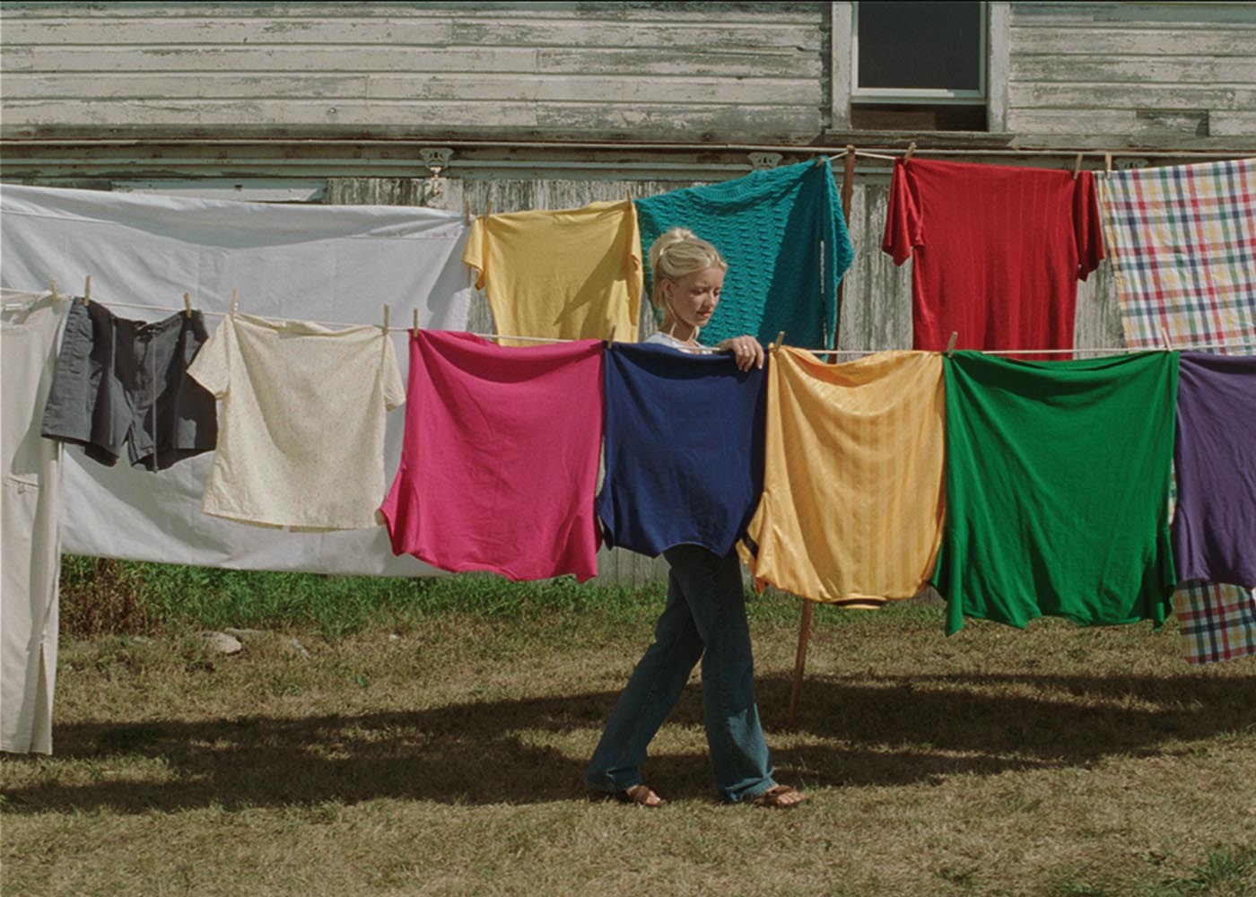
Now let’s look at a digitally acquired image. The image on the left appears flat and desaturated because it is presented in its native state – as an unrendered log-encoded image with camera-specific RGB encoding primaries. But after applying a popular manufacturer-supplied viewing LUT for Rec. 709 displays as its rendering, we get the more “accurate” and pleasing image presented on the right.


These two examples of renderings illustrate that the basic concept of a default scene-referred to display-referred transform is not new. Traditional non-video image processing pipelines have always required a rendering to create a visually pleasing image; ACES is no different in that regard. In fact, ACES reinforces the concept of preserving the original captured image data in as pristine a state as possible. ACES images must also be processed through an appropriate rendering for proper viewing.
ACES Rendering
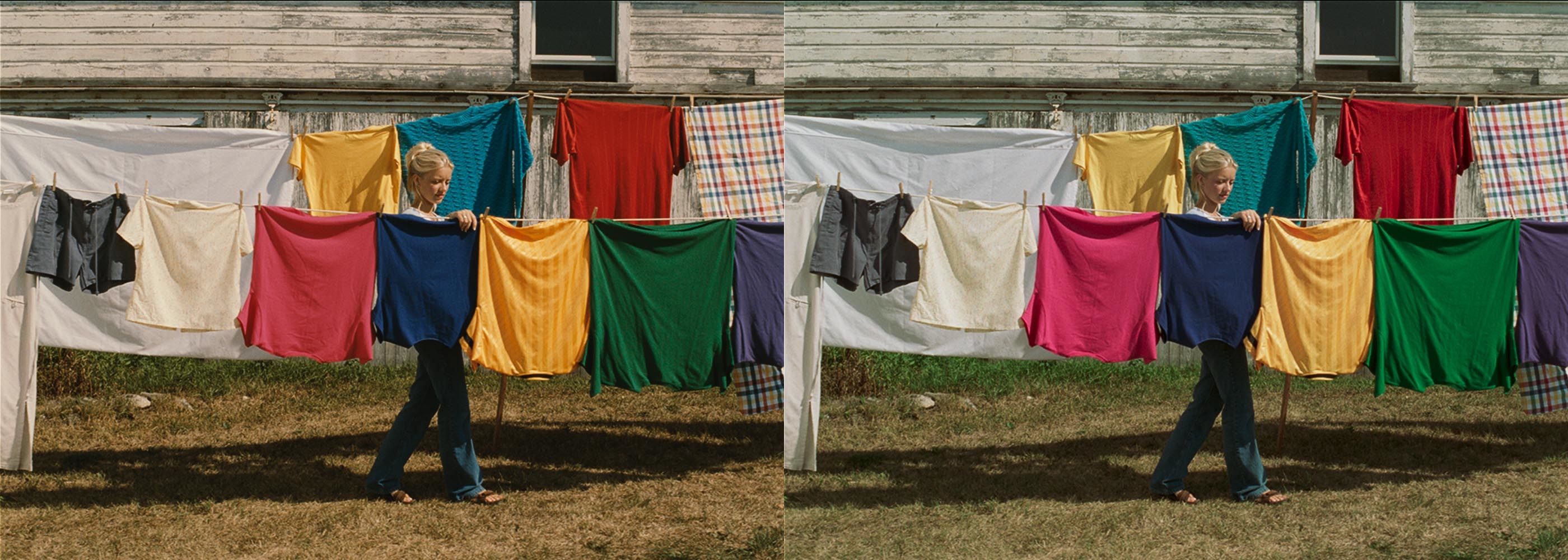
ACES2065-4 (OpenEXR) files are also not intended to be viewed directly. They require processing through an ACES Output Transform in order to be perceived as “correct.” The ACES-supplied rendering is different than that of any of the camera manufacturers or a PFE, just as any individual camera manufacturer’s rendering differs from another. ACES is also different in that there are Input Transforms for all major camera types that convert camera-native image encodings into ACES2065-1. This means that any camera-native image can be viewed through the ACES processing path. To illustrate this point, the same two images from the previous examples are shown again, but this time as they appear when sent through the default ACES rendering.

To produce the above images, each of the native images were put through their appropriate Input Transforms to translate them to an ACES2065-1 encoding, then processed through the ACES Output Transform to Rec. 709 for display. The processing chain for each image is illustrated in the flow diagrams below.


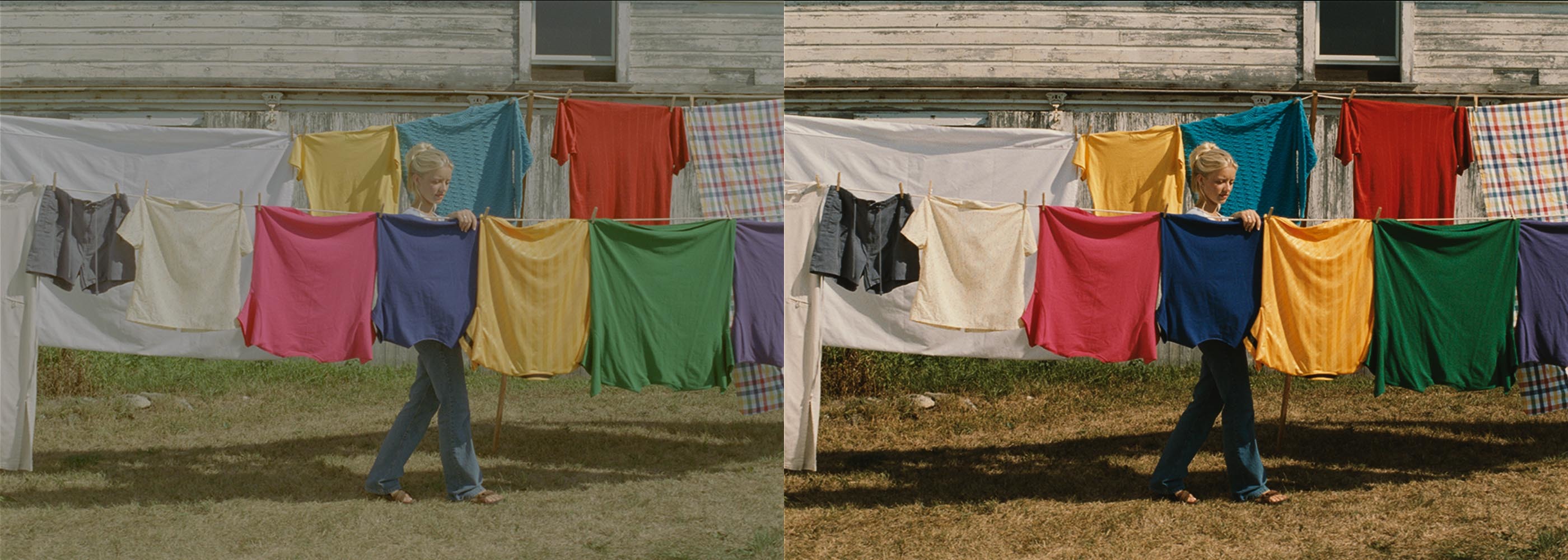
As compared to the their “native” processing paths, the images appear quite different. Below, the pairs are shown again side-by-side for easier comparison. The native camera processing is on the left, and the ACES rendering is on the right.

That the rendered images appear different is not a surprise. The ACES rendering is not intended to match either the PFE or the manufacturer-provided viewing LUT, or any other rendering for that matter. It is intended only to be a starting point from which any desired creative look can be achieved.
Matching an Existing Look
An LMT can be inserted to the ACES rendering chain to move the starting look to match a camera-specific rendering or any other desired starting point, while still remaining within the context of an ACES-based workflow and viewing through the ACES Output Transform.


Transferring Looks
Furthermore, once in ACES, well-designed LMTs are interchangeable. This means that LMTs designed to match a camera-specific rendering can be used for other cameras, or print film emulation LMTs can be used with digital cameras. The possibilities are endless.


The best part about swapping out LMTs is that it does not require creation of any new transforms when using a different input. LMTs are compatible with any well-formed ACES images, whereas non-ACES renderings or customized LUTs are only compatible with particular inputs and outputs. For example, one can’t just apply a PFE to Log C or S-Log3 images and expect them to look anywhere near correct. Furthermore, LUTs output to a particular display device.
In ACES-based workflows, disparate camera-specific encodings are translated into a common encoding space: ACES2065-1. That enables looks to be reusable and applicable within all contexts, regardless of image source.
By now you’re hopefully seeing the power and flexibility afforded by LMTs. Over time, a library of looks can be accumulated and reused within any ACES-based production. If you already have a look library in some other format, it may take a bit of effort to recreate or translate them into ACES LMTs. But this is a process that should only need to be done once.
In the next post, we’ll take a look at what exactly goes inside a LMT, explore how they work and also how to make them.
