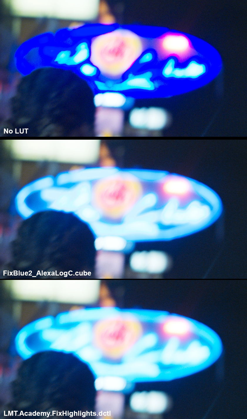
Just wanted to let you know that I have used the LMT Fix Highlight yesterday on a project that was all shot with super saturated color gelled light.
Basically every shot had massive artefacts everywhere, not just highlights.
The LMT worked like a beauty, fixed every artefact and made every shot a lot more pleasing to work, I didn’t have to fight saturation at all.
I will ask permission to post some before and after!
Yes that LMT works like a beauty. Really appreciate having it also. I usually apply it to all shots. As sometimes it’ll fix some weird bokeh that might go unnoticed.
You are putting the LMT in the wrong place. You probably applied it via a node.
This Highlight-Fix-LMT must be applied to the clip via the contextmenu of the clip. NOT in the node tree.
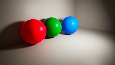
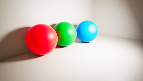
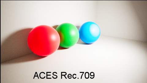
Not sure if this is the same issue exactly, but I am experiencing something similar in blue parts of a CG render. Below is the render as it appears in Nuke with the ACES 1.0.3 OCIO config.
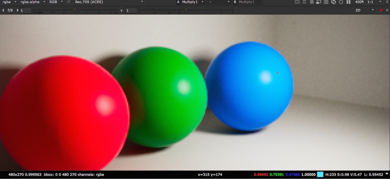
When it is brightened, say with a gain, the area around the highlight on the blue sphere acts quite oddly:
I tried to apply the matrix provided by Scott in this thread by adding it to the OCIO config. Perhaps I am doing that incorrectly. I’m assuming the matrix should go at the end of the input color space for ACEScg:
!
name: role_rendering
family: Utility/Aliases
equalitygroup: “”
bitdepth: 32f
description: |
The ACEScg color space
Not quite sure what you mean with colormetry. Sorry that’s a bit over my head. They are rendered in Vray and the colors are just randomly picked. The blue is <0.96, 0.391, 1.0>
I don’t think this is the same issue as the others in this thread. I would say that what you are seeing is exactly what I would expect from this image.
If you look at the Nuke colour picker reading in the area surrounding the specular highlight on the blue ball, you will see it is ACEScg[0.097, 0.754, 5.473]. This has a much higher blue value than the equivalents for the other balls. The Rec.709 and sRGB ODTs clip above about 16.29, and when applying gain, 5.473 will clearly hit this quite soon (at gain more than 3) causing that area on the blue ball to flatten and desaturate, which is exactly what I see.
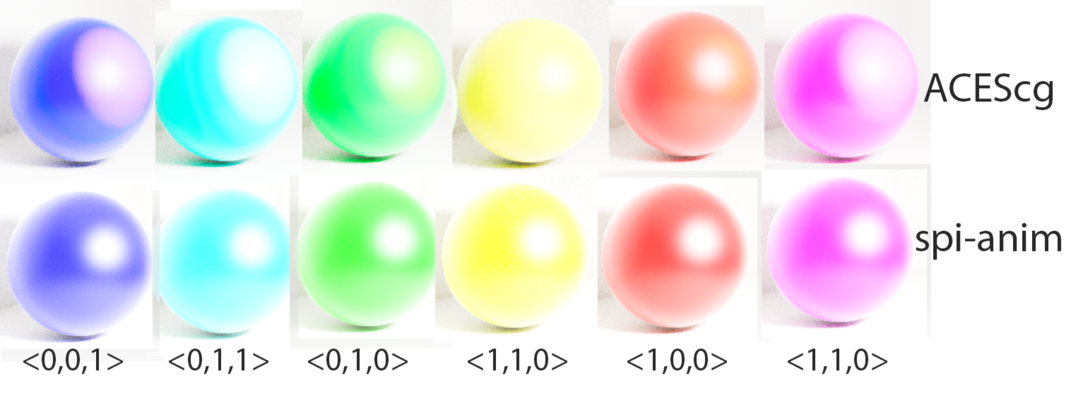
Yes it is quite bright on that one sphere. I’m trying to test what happens when the exposure is raised on the image. As a further test I removed the other spheres and then fed in different colors to the sphere. In the image below I have rendered the single sphere with the exposure raised up to 5 to demonstrate the behavior. You can see these colors in ACEScg compared with spi-anim. The behavior of spi-anim is what I would expect to happen, and the behavior of ACEScg seems unusual. Notice for example how you get a big white :“highlight” around teal and magenta, and then yellow in the big “highlights” for the green and red (on either side of yellow). None of that happens in spi-anim (or in sRGB 2.2 gamma). So it seems to me that something odd is going on with ACES. Just trying to figure out what that may be.
Is that 5 stops? Linear mult by 5? Or something else? “Exposure raised up to 5” is ambiguous.
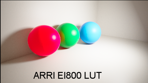
Part of what you are seeing is the difference between the overexposure handling of the picture rendering in the ACES RRT/ODT combo, and that in spi-anim. There is no one “right” way to map scene to display referred. If for example you use an OCIOColourSpace node to transform from ACEScg to LogC Wide Gamut with increased exposure, you will see a different result again. The ARRI LUT handles the blue ball in an arguable more aesthetically pleasing way, but creates unpleasant artefacts on the red one:
Both the above images have linear mult of 5 applied in ACEScg.
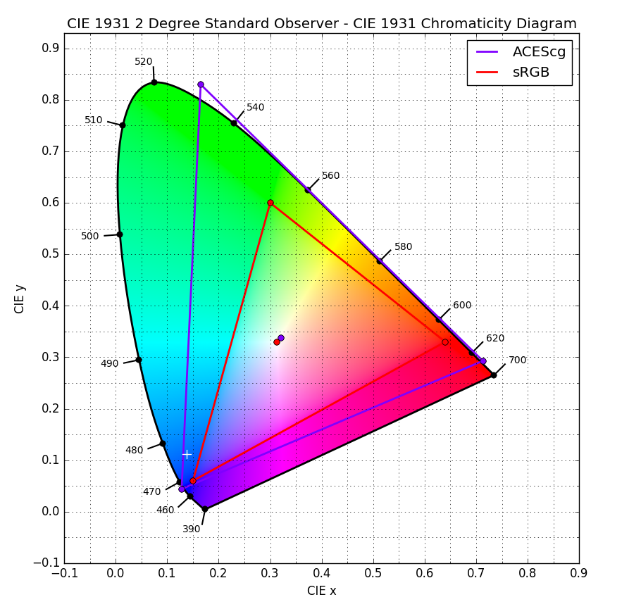
But also, I believe spi-anim expects sRGB primaries, and your image has ACEScg primaries (or at least the ACES 1.0.3 config is treating it that way). If spi-anim is then interpreting those same code values as having sRGB primaries, they will appear to be very desaturated compared to the colours they represent in ACEScg. If you apply an ACEScg to sRGB matrix to the image first (which arguably is the correct thing to do) the result of raising exposure in spi-anim is far less visually pleasing, going very quickly into clippy, saturated colours, with no visible specular.
For reference, the ACEScg to sRGB matrix, using CAT02 is:
1.70507964 -0.62423346 -0.08084618
-0.12970053 1.13846855 -0.00876802
-0.02416634 -0.12461416 1.14878050
Multiply that matrix by [0.097, 0.754, 5.473] and you get [-0.7477501, 0.797837, 6.190972]. So your CG render has produced a colour which is way outside the sRGB gamut. So it’s up for debate what the “best” way to map that to an sRGB/Rec.709 display is even before you increase the exposure.
For the primaries that has to do with the input colors on the materials, right? So rather than simply picking a color for the diffuse (which I believe would mean it is an sRGB primary) the color would need to have a color space conversion applied to it to make it ACEScg. Do you know what the correct input/output color spaces would need to be for a texture color? I’m thinking input: “Input - Generic - sRGB - Texture” (sRGB to linear) and output: “role_scene_linear” (ACEScg to ACES2065-1).
I think I figured out what the problem was. I tried reading ACES from the Maya Color Management prefs. There if I load ACES with integrated SynColor and set the view transform to OCIO view transform ACES RRT v1.0, it works fine and I do not get the blown out color. If I instead load the ACES OCIO (ACES v1.0.3) I get the problem shown above. So the issue appears to be the view transform.
The problem is that while I can use SynColor in Maya, I need OCIO for Nuke. I see that SynColor appears to be using the file ACES_to_sRGB_1.0.ctf. Does anyone know how to convert this .ctf file to something OCIO can read?
I agree with what Nick wrote above, the whitened area will vary with the color of the object due to the different behavior of the various rendering transforms (ACES, spi-anim, ARRI, etc.) as colors move off the top of the gamut.
That said, although the OCIO ACES config is quite good, it sounds like you’re running into a known issue – as colors get very bright they lose accuracy.
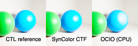
I’m attaching an example image so others can follow what we’re talking about. This is a region of your EXR, with the exposure gained up by 5x. On the left is the result of the Academy sRGB Output Transform CTL (ground truth), in the middle is what Maya/Flame/Lustre would give (SynColor CTF), and on the right is what the ACES config in OCIO would give. (I specified the OCIO CPU renderer since the OCIO GPU renderer has other known problems.) You can see that the Maya result matches the CTL reference but the OCIO result is wrong in the blue highlights.
Regarding your question about Nuke, currently there is no easy way to apply a CTF in Nuke. You could bake it out into a LUT, but then you’d run into the same problems that the OCIO config has. The reason the CTF works better is because it is more of an “exact math” implementation of the ACES CTL code rather than baking down into a LUT-based representation.
However, the SynColor SDK is included in the Maya DevKit, so it is possible to write plug-ins that would allow you to apply CTFs (and therefore ACES transforms) at full accuracy (and high speed) in other applications. I know some facilities have done this but I realize it requires more work than one would like.